Note:
This article heavily relies on singular sources to cite information.
Note:
This article lacks adequate inline citations.
This article has not been peer reviewed! Learn why peer reviewing is important.
Contents
Abstract
As participants in the AIAA Design, Build, Fly competition, UNSW Skylabs stands to gain a significant advantage from the implementation of a number of, non-trivial, but technically well-understood improvements to the design and manufacture of our aircraft. This paper will explore a number of these improvements, including the use of composites and high-strength lightweight materials, wingtip devices, higher-performance flaps, a twin-engine design, and impact-resistant delivery for sensitive payloads.
Introduction
With respect to airframe, aerofoil, and other aerostructure manufacture, evaluating composites as a high-strength, lightweight material is a key consideration. Major aeronautical engineering companies such as Lockheed Mart and Boiing already make extensive use of composites, due to their composability in material properties and ability to be novelly engineered to meet specific requirements (within reason).


Wingtip devices are another key consideration, as they can significantly reduce drag and hence improve fuel efficiency. Within the context of the DBF competition (as UNSW Skylabs aircraft rely on electrical power for propulsion), the margin gained by the implementation of particular wingtip devices could be significant, since battery capacity is limited and exhibits diminishing returns in power storage vs. size.
Whilst UNSW Skylabs' existing DBF aircraft already feature (plain) flaps, the implementation of modern, higher-performance (albeit also more mechanically complex) flaps, as implemented in a variety of modern aircraft, could provide a significant increase in lift-to-drag ratio. This would be particularly useful in a case where short takeoff or arrested landing capability is required. In this paper, we explore the split, slotted, fowler, and double-slotted fowler flap types, as well as their respective advantages and disadvantages.
A key component of reliable, dependable, and resilient aircraft in the modern day is the implementation of a fly-by-wire system. The flight computer, and its corollary, FBW, are responsible for translating pilot (or guidance computer⌜absolutely not im not going to jail⌟) input into control surface deflection, to result in predictable consequent angular motion. Additionally, FBW can be used to implement a variety of flight control parameters, such as auto-trimming, flight envelope protection (incl. G-force limiting), and stability augmentation. In particular, a sufficiently adaptive FBW is also able to provide a degree of fault tolerance, by reacting to and compensating for control surface failures, or structural damage. This paper will examine more specifically the tradeoffs (especially the need for redundancy) and challenges FBW presents, and how (from an avionics perspective) such a system could be implemented in UNSW Skylabs' aircraft. Our proposal suggests the use of a high-performance, realtime, flight dynamics simulation software, to build and test avionics software systems (it's kerbal space program).
This paper will draw on existing literature, as well as the collective experience of UNSW Skylabs, to evaluate considerations we have made and proposals we have suggested.
Keywords: Aeronautical Design, Composites, Wingtip Devices, Flaps, Flight Computers, Fly-by-Wire, Twin-Engine Aircraft, CFD, Simulation
Composites and High-Strength Lightweight Materials
Preamble
UNSW Skylabs currently manufactures manufactures its aircraft out of wood and solar film. A significant avenue of improvement in this regard is the incoroporation of composites and high-strength lightweight materials into aerostructures. Wood suffers from a number of disadvantages, including a relatively low strength to volume ratio, and a tendency to warp and degrade over time. It may be worth exploring further alternatives to wooden airframes, such as aluminium honeycombing instead of wooden ribs in the wings. Relatedly, solar film, whilst lightweight, does not hold its shape, is not particularly strong, and is prone to tearing and puncturing.
Modern composite manufacturing involves a number of techniques, including hand layup, resin infusion, and pre-pregs, each method of which is fit to purpose for a range of turnaround times, sizes, and manufacturing precision[3]. This paper will focus on composite manufacturing methods that are most applicable to UNSW Skylabs' aircraft, and will explore the manufacturing process behind each. Particularly, we will assume the fibre laminate intended for resin application is carbon fibre, as it looks sicks as hell, although in principle, other fibre materials used in composites, like fibreglass or aramid fibre, could be used just as well.
Composite Manufacture — Vacuum Infusion
Vacuum infusion is a composite manufacturing method that involves the use of a vacuum to draw resin through a laminate, which is then cured to form a composite part. The process begins with the placement of a dry fibre laminate into a mould, which is then sealed with a vacuum bag[3]. The vacuum is then applied to the bag, which draws in the resin on the other side through the laminate, wetting the fibres. The resin is then cured, either through the application of heat, air-drying, or through the use of a UV light, depending on the resin used[3]. Vacuum infusion is a relatively low-cost method of composite manufacture, and is particularly well-suited to the production of large, complex parts[3].
Composite Manufacture — Resin Transfer Moulding (RTM)
Based on the same principles as vacuum infusion, RTM relies on a pump to push resin through the fibre sheet at a significantly higher pressure[3]. Especially under high pressure, RTM usually involves a mould which is bolted together or hydraulically clamped[3]. In conjunction with high temperature injection, cycle times tend to be shorter than vacuum infusion, and the process is more suited to high-volume production[3].
Composite Manufacture — Pre-Preg
A “pre-preg” is a fibre sheet that has had the optimal amount of resin applied to it, and has been partially cured ahead of time[3]. To prevent degradation, pre-pregs are usually stored in a freezer until they are ready to be used[3]. Once ready for use, the pre-preg is thawed, and laminated onto a mould, which is then cured to form the final composite[3]. Curing of a pre-preg usually involves “baking” in an oven or autoclave, wherein the elevated temperature re-catalyses the curing reaction, letting the resin flow and harden, resulting in a highly precise resin/fibre content[3].
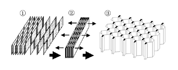
Metal Honeycombing
Metal honeycombs, commonly found in honeycomb panelling, are a lightweight, relatively inexpensive, high-strength material that can be used in a variety of applications, including aerostructures. It's low cost to strength ratio, and high strength to weight ratio, make it an attractive alternative to traditional material construction. The manufacture of the structure is relatively simple, involving cutting a sheet of metal in a particular pattern of thin connected slices, then extending out the workpiece to form a honeycomb structure— a technique known as the extension method[4]. Commonly, this is done with aluminium, as it is a versatile, malleable, and relatively strong material that can be easily formed into a honeycomb structure. Generally, the honeycomb structure is then sandwiched between two sheets of material, forming honeycomb panelling, however, in the context of UNSW Skylabs' aircraft, due to the small scale of our aircraft, it may be more reasonable to use honeycombing within the whole internal structure of the wing, rather than as a sandwich panel.
Wingtip Devices
Aerodynamic Principles
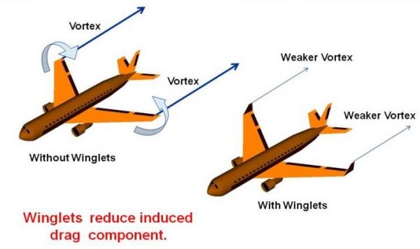
Most modern aircraft (including those designed and flown by UNSW Skylabs) comprise a pair of straight primary wings, which extend laterally from the fuselage. As a consequence, towards the tips of the wings, the denser, higher pressure air beneath the wing tends to flow around the wingtip and up towards the lower pressure air above the wing, forming a vortex[5]. The phenomenon of wingtip vortices, also known as downwash, can be a concern, as the decreased chordwise airflow (and corresponding increased spanwise flow) can markedly increase drag[5][6]. Particularly with larger wings, this reduces the effectiveness of the aerofoil towards the wingtip in generating lift, and hence can significantly decrease the lift-to-drag ratio. The primary goal of wingtip devices is to alleviate this aerodynamic phenomenon, by introducing a physical barrier that prevents some of the high pressure air (below) from moving over the wing and interacting with the low pressure air (above)[7]. A challenge with the implementation of wingtip devices, specifically in the case of small aircraft such as those flown by UNSW Skylabs, is creating a sufficient improvement in induced drag, whilst minimising (or offsetting) the increase in profile drag.
We will explore three types of wingtip devices in this paper: blended winglets, horner (hoerner) wingtips⌜Disambiguation: Not to be confused with Lippisch-Ohren wingtip devices, which often go by the same name.⌟, and raked wingtips. Our belief is that we should explore a range of wingtip devices to better inform design decisions such that aerodynamic performance on Skylabs' aircraft is maximised.
Blended Winglets
A natural progression from the canted winglet, the blended winglet substitutes the sharp cant angle with a smooth chord variation across the transition area between the wing and the winglet, which, compared to the traditional canted winglet, reduces the vortex concentration caused by disruption in boundary layer airflow at the interior angle of the blending region, decreasing interference drag[8].
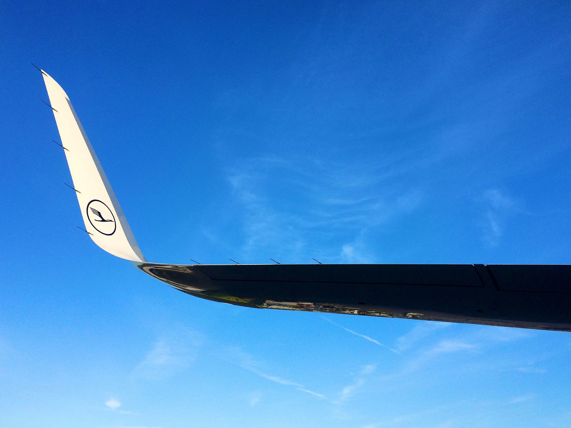
By Kiefer. from Frankfurt, Germany - Flickr, CC BY-SA 2.0, https://commons.wikimedia.org/w/index.php?curid=47140264
Horner Wingtips
Contrary to conventional wing-extension based wingtip devices, the Horner wingtip comprises a smooth, upwards taper towards the tip of the wing[9]. By tapering the wing upwards, the Horner wingtip creates a region of relative low pressure within, which delays the onset of the wingtip vortex, and hence increases the effective wingspan of the aircraft[10]. Horner wingtips have demonstrated a measurable increase in effective wingspan, especially amongst (hehe among us) smaller aircraft, specifically, where Skylabs' aircraft stands to benefit the most.
Raked Wingtips
The raked wingtip comprises a wingtip extension that is has a high angled leading edge sweep, and frequently, also a trailing edge sweep. Similarly to the blended winglet, the raked wingtip is designed to reduce the intensity of the wingtip vortex, and hence reduce induced drag[11]. Notably with a trailing edge sweep, the raked wingtip also directs the wingtip vortex behind and outward of the wing, further reducing induced drag[11].
Higher-Performance Flaps
Aerodynamic Principles
A flap is a dedicated control surface that deflects downwards from the trailing edge of the wing, which causes an increase in the pressure below the wing, and hence increases lift, which is particularly useful in situations where a high lift coefficient is required, such as during takeoff and landing. Additionally, flaps can be used to increase the maximum lift coefficient of the wing, and hence decrease the stall speed of the aircraft, or to provide a small improvement in turn radius. However, a consequence of flap deflection is an corollary increase in both induced and profile drag, which presents the primary challenge in effectively implementing flaps— to retain the lifting characteristics of the wing, whilst minimising the drag penalty. By modifiying the design on the flap, a number of airflow characteristics can be altered, which can provide a significant improvement in lift-to-drag ratio. This paper will explore a number of flap types, including the split, slotted, fowler, and double-slotted fowler flaps, and evaluate their respective advantages and disadvantages.
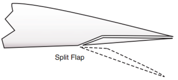
Split Flaps
A split flap can effectively be thought of as a cutout of a portion of the wing towards the trailing edge[14]. This surface is hinged towards the leading edge and deflects downwards to act as a flap[14]. A major benefit to this approach is the mechanical simplicity of the design, and the minimal impact on the existing wing structure. Particularly, the space between the wing and the flap can be used to house the flap actuator (a piston or otherwise) which can be a mechanically advantageous in terms of both actuation and the design of the aircraft.
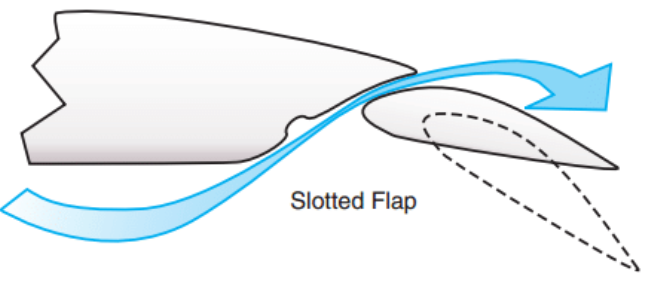
Slotted Flaps
The slotted flap comprises a portion of the trailing edge of the wing as a rectangular cutout[14]. Mechanically, the slotted flap resembles the plain flap, however, the slotted flap includes a gap between the wing and the flap, which allows high pressure air from below the wing to flow over the top of the flap[14]. This has the effect of maintaining boundary layer airflow, which is beneficial to the lift characteristics of the wing, and hence the lift-to-drag ratio[14].
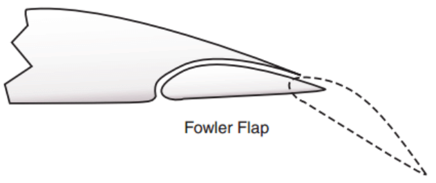
Fowler Flaps
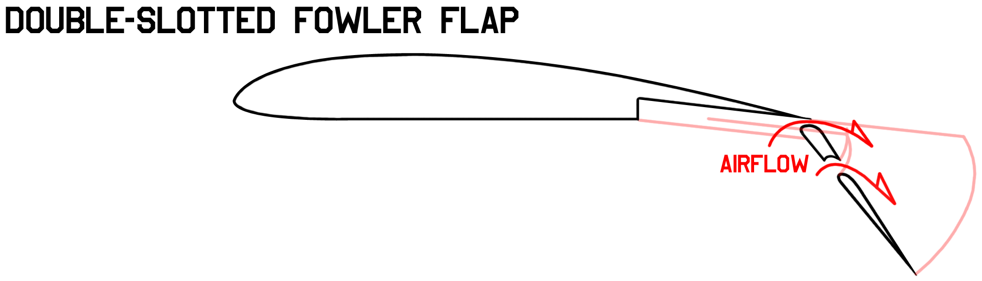
The fowler flap appears similar to the split flap in placement, however its actuation involves extending the flap outboard and behind into an intermediate position, before deflecting downwards[14]. This mechanical complexity allows the fowler flap to increase the wing area, and greatly increase lift, however, the mechanism is more complex, and the space and mass required for the flap actuator is greater. The design of fowler flap is also extended through a double-slotted fowler flap, which combines the boundary flow benefits of the slotted flap with the increased lift of the fowler flap, by dividing the flap into two sections, and allowing high pressure air to flow over the top of and under through the flap. Whilst highly applicable to larger aircraft, the fowler flap may not be as suitable for smaller aircraft, such as those flown by UNSW Skylabs, due to the increased complexity and mass of the mechanism and smaller wing area.
Aerodynamic Analysis
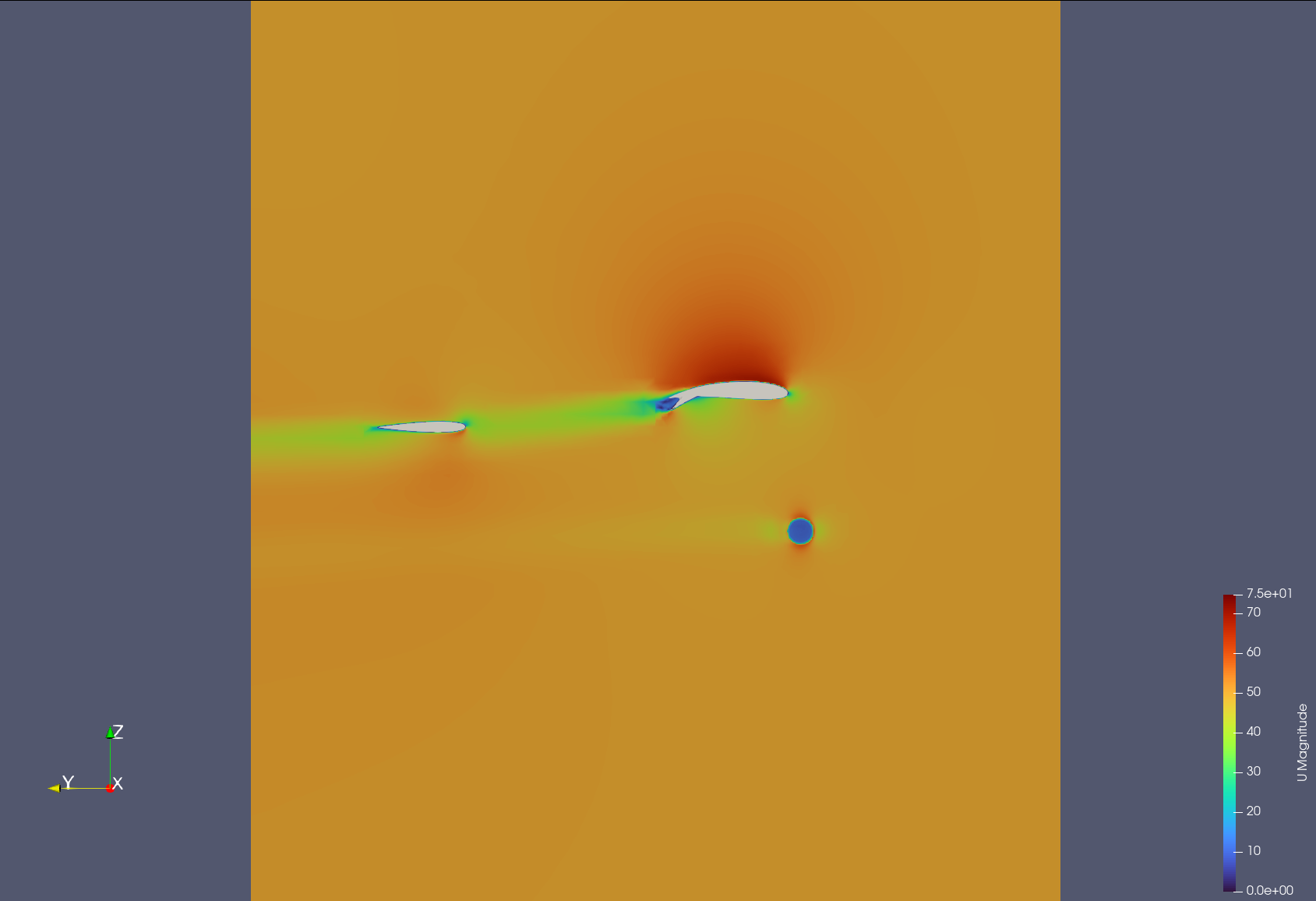
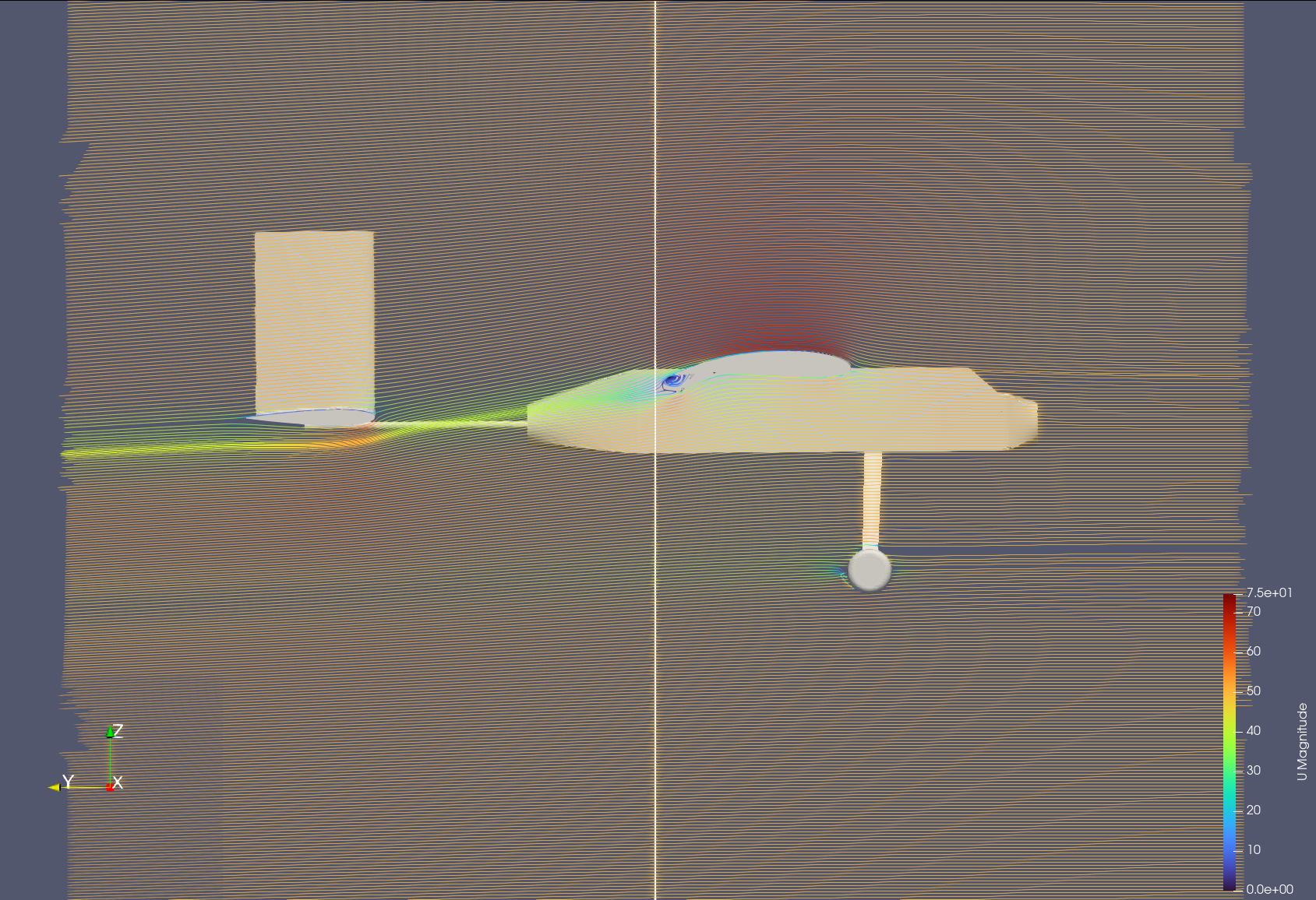
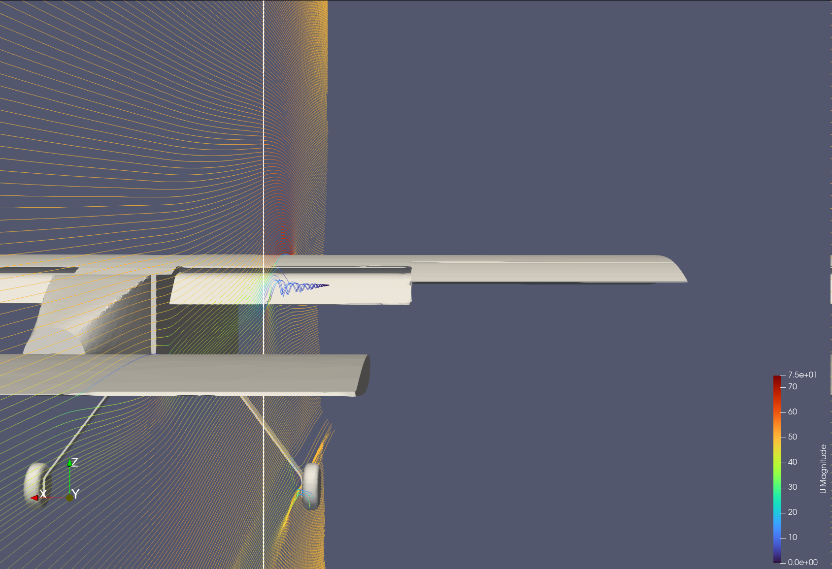
UNSW Skylabs' primary DBF aircraft currently feature a plain flap, which is a mechanically simple, but still functional approach to flap implementation. It should be noted that, possibly due to inadequate CFD during the design phase, the current implementation of flaps is not especially aerodynamically efficient. With flaps extended at 25°, we have conducted a rudimentary airflow and aerodynamic force analysis using FreeCAD-cfdof / OpenFOAM. Our post-processing results are created using Paraview, and are shown below.
Flight Computer / Fly-By-Wire
Preamble
Historically, and in present, UNSW Skylabs' aircraft flight controls have been mechanically actuated, forwarding pilot input directly to control surfaces through a series of mechanical linkages. As a consequence, the aircraft have been limited in the complexity of flight control systems that can be implemented, and hence the degree of control that can be exerted over the aircraft. Additionally, UNSW Skylabs has experienced a number of incidents where mechanical and/or structural failure has resulted in loss of control, or in some cases, catastrophic failure.
Single Control Surface Multi-Axis Control
The first step to effectively implementing a flight controller is to implement a software system that acts as an intermediary between the pilot and the control surfaces. This not only allows us to combine control inputs in multiple axes, but in combination with a gyroscope and accelerometer, can be used to to effectively implement a reactive fly-by-wire.
By interpolating between control inputs in multiple axes, the full range of control surfaces can be actuated to provide a flight computer with the maximum degree of control over the aircraft. A common example of such a type of control surface is the elevon, which combines the functions of both the elevator and the aileron. Such a configuration provides some level of additional roll authority, which can be particularly useful in high-AoA situations, wherein the primary wing may begin to stall. Additionally, modern aircraft make use of more than just the three traditional control surfaces (elevator, aileron, rudder), through more advanced control surfaces such as the leading edge flaps, slats, and canards, which provides the flight computer with a greater degree of control over the aircraft. To implement such a control system, we propose a microcontroller subsystem that translates receiver input, passing it to the flight computer, which then actuates the control surfaces.
For each control surface to determine it's calculated deflection angle, the flight computer will compute, based on designated axis weights, how much each axial input will contribute to the overall deflection. Based on the following equation,
, with , we can interpolate between the axial inputs to determine the deflection angle of the control surface (à la KSP + FAR). Briefly, this means we can define an elevon with .
todo: pwm the controller we use arduino code
Flight Envelope Protection
A key consideration in the implementation of a flight computer is the ability to protect the aircraft from entering into a stall, or from exceeding the maximum G-force limit. Particularly at high speeds, a given deflection of a control surface exerts a greater force on the aircraft, which could cause the structure of the aircraft weaken by exceeding the maximum G-force limit, or more catastrophically disintegrate midair. To prevent this, the flight computer can be programmed to dynamically limit the maximum deflection of the control surfaces, and hence the maximum force that can be exerted on the aircraft. Generically, this can be enforced by ensuring
(derived from ), preventing the aircraft from exceeding its maximum G-force limit. A better approach worth exploring would be to split the G-force calculation into axial components, to prevent the over-limiting of control authority in any particular direction, or even more ideally, an approximate realtime finite element model. Another important inclusion in the flight envelope protection system is the ability to prevent the aircraft from entering into a stall, by limiting the maximum angle of attack the aircraft can achieve. By preventing the aircraft from exceeding the critical angle of attack, the flight computer can prevent the aircraft from entering into a stall, and hence prevent a loss of control. With
, we can effectively restrict the maximum angle of attack the aircraft can achieve, and hence prevent the aircraft from entering into a stall. Additionally, it forces the deflection angle in the opposite direction should the aircraft exceed the critical angle of attack. It is worth noting that the AoA limit need not be a constant, but can be dynamically adjusted based on the current flight conditions, such as airspeed and altitude. A similar limiting function can be applied to the maximum G-force limit, which should be explored further.
Stability Augmentation
A major technical advantage UNSW Skylabs could benefit from in the implementation of a flight computer is the ability to provide stability augmentation. By directing the aircraft in the opposite direction to the angular acceleration with a low weight modifier, the flight computer can provide a degree of stability augmentation, simplifying the task of the pilot, and providing a more predictable flight experience. In theory, SAS is as simple as
. A precursor to fly-by-wire, SAS has a simpler implementation both in software and hardware, and can act as a stepping stone to a more complex FBW system. For brevity, as this paper is more exploratory towards the implementation of a FBW system, we will not delve into the specifics of SAS.
Full Fly-by-Wire
The implementation of a full fly-by-wire system is a significant challenge with a significant benefit, but a number of tradeoffs. A primary benefit of FBW is the complete pilot predictability and control over the aircraft, enabling a more precise and predictable flight experience. Additionally, FBW can be used to auto-trim the aircraft, providing constant attitude control, whlist also providing a very fine grained level of detail in control surface deflection, hence reducing the workload on the pilot. In terms of controllability, there are aircraft that exhibit static instability, which would otherwise be impossible for a pilot to control without a FBW system. At least in the near future, it may be worth at least designing UNSW Skylabs' aircraft to be statically neutral in either pitch or roll, to provide a greater degree of manoevrability. which would be difficult to control without a FBW system. UNSW Skylabs' aicraft are propeller driven— the aircraft experiences a moment from the propeller rotation, which can be compensated for by the FBW system. Should UNSW Skylabs decide, in future, to move towards a twin-engine aircraft, the FBW system can be adjusted to provide differential thrust, which can be used to provide beneficial control and manoevrability characteristics. Most relevantly for UNSW Skylabs, perhaps, is the level of fault tolerance a corrective FBW system can provide, by reacting to and compensating for control surface failures, or structural damage.
However, FBW is significantly more complex than a mechanical control system, and hence requires a greater degree of redundancy to ensure the system is reliable. Moreover, the implementation of a FBW system requires a significant amount of software development, and hence a significant amount of testing to actually ensure that the system is reliable.
We propose the implementation of a novel reactive-corrective FBW system, which responds to the motion caused by a particular configuration of control surface deflections, and then corrects for the motion with a binary search to identify the optimal control surface deflection. The FBW will cache the optimal control surface deflection and map them into a lookup table.
References
1. Twitter. (2024). "lockheed martin vtuber logo". [online] Available at: https://x.com/wazza_razza73/status/1780800311344713906note: not an academic source.
2. Twitter. (2024). ‘I made Boeing’. [online] Available at: https://x.com/mikoonnn/status/1780931050568564882note: not an academic source.
3. Chris (2020). Composite Manufacturing Methods. [online] Explore Composites! Available at: https://explorecomposites.com/articles/design-for-composites/basics-manufacturing-methods/note: not an academic source.
4. Wang, L., Saito, K., Gotou, Y. and Okabe, Y. (2017). Design and fabrication of aluminum honeycomb structures based on origami technology. [online] ResearchGate. Available at: https://www.researchgate.net/publication/317420555_Design_and_fabrication_of_aluminum_honeycomb_structures_based_on_origami_technology .
5. SKYbrary Aviation Safety. (2021). Induced Drag. [online] Available at: https://skybrary.aero/articles/induced-dragnote: not an academic source.
6. Glenn Research Center | NASA. (n.d.). Downwash Effects on Lift. [online] Available at: https://www1.grc.nasa.gov/beginners-guide-to-aeronautics/downwash-effects-on-lift/.
7. Dasilva, M. (2023). Winglets. [online] Glenn Research Center | NASA. Available at: https://www1.grc.nasa.gov/beginners-guide-to-aeronautics/winglets/.
8. Wikipedia Contributors (2019). Wingtip Device. [online] Wikipedia. Available at: https://en.wikipedia.org/wiki/Wingtip_devicenote: not an academic source.
9. Heintz, C. (n.d.). Anatomy of a STOL Aircraft. [online] www.zenithair.com. Available at: http://www.zenithair.com/stolch801/design/design.html.
10. Kämpf, P. (2017a). How Do Hoerner Wingtips Work? [online] Aviation Stack Exchange. Available at: https://aviation.stackexchange.com/a/35071note: not an academic source.
11. “aeroalias” (2015). How does the raked wingtip of the Boeing 787 work? [online] Aviation Stack Exchange. Available at: https://aviation.stackexchange.com/a/19079.
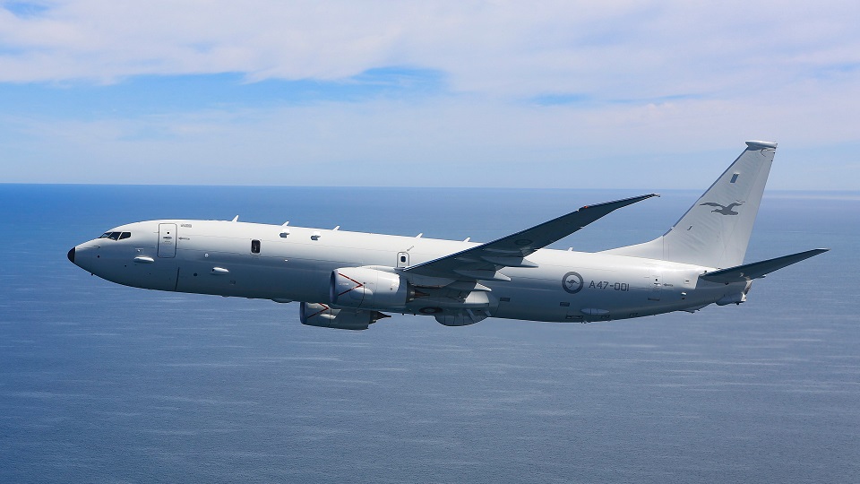
12. Royal Australian Air Force (2016). P-8A Poseidon | Air Force. [online] Airforce.gov.au. Available at: https://www.airforce.gov.au/aircraft/p-8a-poseidon.
13. Mehta, D. (2022). Why Winglets Are Typically Only Found on Larger Aircraft. [online] Simple Flying. Available at: https://simpleflying.com/why-winglets-are-typically-only-found-on-larger-aircraft/note: not an academic source.
14. Wikipedia Contributors (2019b). Flap (aeronautics). [online] Wikipedia. Available at: https://en.wikipedia.org/wiki/Flap_(aeronautics).
15. Singhal, A. (2016). Figure 13: Different types of flaps [online] ResearchGate. Available at: https://www.researchgate.net/figure/Different-types-of-flaps-Source_fig21_295402099.
16. Wikipedia Contributors (2021). Elevon. [online] Wikipedia. Available at: https://en.wikipedia.org/wiki/Elevonnote: not an academic source.
17. Wikipedia Contributors (2019). Parasitic drag. [online] Wikipedia. Available at: https://en.wikipedia.org/wiki/Parasitic_drag.
18. Aviation Partners, Inc. (n.d.). Types of Blended Winglets | Aviation Partners. [online] Available at: https://www.aviationpartners.com/aircraft-winglets/types-blended-winglets/.
19. SKYbrary (2021). Drag. [online] SKYbrary Aviation Safety. Available at: https://skybrary.aero/articles/drag.
References courtesy of MyBib.